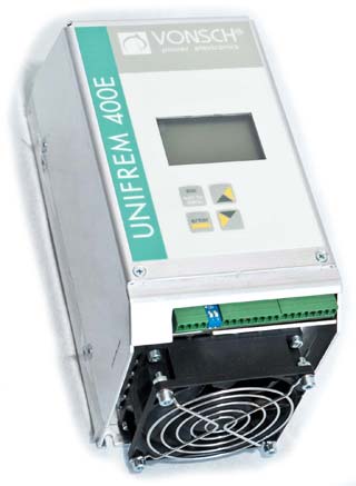
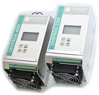
UNIFREM 400 E is the latest generation of small
dimensions frequency converters family.
UNIFREM 400 E is made for 3 x 400 V supply,
available up to 3 kW. All UNIFREM converters
allow high-performance scalar (V/f) control. UNIFREM 400 E drives are
designed to solve most of drive problems in the
industrial applications. The family
is specified by its user-friendly settings and control, users are
guided by the graphic display.
The latest generation of MITSUBISHI power electronics
has been used for minimization of losses
while allowing higher switching frequency. Grid
disturbance is kept to a minimum.
Features and advantages of UNIFREM E


High resistance against fault immiting
UNIFREM converters include protection against overvoltage, undervoltage, current overloading of converter, short circuit between input phases and overheating.
Input and output phase loss are detected as well. Overheating of motor is suppressed by calculating the heat integral of the motor.
Minimal disturbance to the supply power grid
Optional input commutation chokes are lowering the harmonic distortion (EN 61800–3).
Standard use of noise suppresing filters ensures minimal disturbance to the power grid (EN 61000–6-4).
Minimal losses
Use of the newest power electronics has lowered and minimalized converter losses and power grid disturbance.
Smaller dimensions
By the use of power optimized heat sink together with improved heat-transfer-targeted placement of power components smaller dimensions have been achieved.
High reliability
The latest generation power capacitors with extended operating temperature and lifetime by 20% as well as the newest power electronics components have been used.
The cooling fans with high-quality bearings ensure longer lifetime and lower noise level.
Rich software features
- Predefined nameplate data for common induction motor types
- Reliable, fast and simple motor parameter identification
- High performance V/f control - slip compensation, slip limit, resonance damping..
- Current limit (motoric, regenerative, for slow and fast load transients)
- Kinetic backup, ride-through capabilities for short supply power failures
- Flying start
- 3 braking modes (braking module, flux braking, dynamic deceleration)
- Universal and fully configurable system of inputs and outputs
- 4 binary inputs
- 2 binary outputs with configurable time delays
- 2 analog inputs, current or voltage type
- 1 analog output, configurable for any process variable
- User macros - preset configurations:
- for standard schemas of control (manual control, binary, up-down commands, PID regulation, MODBUS, ...)
- for control basic kinds of load ( pump, fan, conveyor/travel, extruder)
- PLC functions
- 4 universal logical blocks, user configurable (AND, OR, XOR, RS flip-flop, comparison operators)
- 4 universal numerické blocks, user configurable (addition, subtraction, multiplication, min, max, 1st order filter, abs, multiplexor)
- Universal process PID controller (various action variables, rich configuration possibilities
- 2 Multifunctional limit switches
- Advanced parameter management, 4 independent parameter sets, switchable on-the-run
- MODBUS RTU communication protocol
- built-in USB port for configuration, diagnostics and parameter management with VONSCH Drive Studio application for Windows®
Events and faults history
Configurable history of faults, warnings and other events with capacity of latest 256 items.
Commands
- Interactive graphic display
- Parameters structure allows sinple configuration, while watching the mutual dependencies of the parameters
- Access to the parameters and the diagnostics can be done in severak ways (integrated display, MODBUS RTU, external manual panel UNIPANEL)
Communication with the operators:
Inteligent user interface designed for easy configuration and reliable diagnostic using the inbuilt graphical LCD display.
VONSCH Drive Studio
Application for configuration, diagnostics and archiving of settings to PC.
It allows: firmware upgrade, process diagnostic "black box" data.
Diagnostics of faults and events helps the operator to solve the problems and avoid the future ones.
Standard equipment:
Noise suppresing filter
Eliminates disturbances to the power grid
(EN 61000–6-4)
Brake module
Electronics for brake resistor control used in generator mode of operation
Options:
Three phase commutation choke KT1

Minimization of harmonic currents from the power grid.
(EN 61800–3)
Motor (output) choke MT1

Output motor chokes are used in case when the distance between the converter and the motor is higher than 100m (non-shielded cable) or 50m (shielded cable).
Cable capacitance effects are eliminated by the motor choke or sine filter.
Brake resistor BO1

Ensures dissipation of kinetic energy in the regenerative mode of motor operation.
Sine filter SF1

Sine filter filters the output PWM voltage of the inverter to the sine wave of variable frequency and amplitude.
This will limit the peak current and capacitive motor insulation stress. When using the EMC sinus filter, it is not necessary to use the shielded cable.
It is necessary to set the switching frequency of IGBT power elements to at least 4 kHz, when using the Sine filter!
Technical data
| Type of the converter |
M ~ constant load | Nominal input current of the converter ININ [A] |
| Motor output rating PNOM [kW] | Nominal output current of the converter INK [A] |
Nominal output current of the converter INK60 [A] | Nominal output current of the converter INK2 [A] |
| UNIFREM 400E 0750 | 0.75 | 2.2 | 3.3 | 4.4 | 3.1 |
| UNIFREM 400E 1100 | 1.1 | 3.1 | 4.65 | 6.2 | 4.2 |
| UNIFREM 400E 1500 | 1.5 | 4.2 | 6.3 | 8.4 | 5.7 |
| UNIFREM 400E 2200 | 2.2 | 5.7 | 8.55 | 11.4 | 7.0 |
| UNIFREM 400E 3000 | 3.0 | 7.0 | 10.5 | 14.0 | 9.3 |
| INK | - nominal output current of the converter for constant load |
|---|
| INK60 | - nominal output current of the converter that is equalled 1,5 x InK for the duration of 60 s each 10 min |
|---|
| INK2 | - maximal output current of the converter that is equalled 2 x InK for the duration of 2 each 15 s |
|---|
For frequency converters UNIFREM 400 of rated power below 11 kW, please visit
UNIFREM 400 M. If looking for converters above 11 kW please visit
UNIFREM 400 or
UNIFREM 400 (>200kW) for converters rated higher than 200 kW.
Dimensions
| Type of the converter |
height [mm] |
width[mm] |
depth [mm] |
Inbuilt fan |
| UNIFREM 400E 0750 | 228 | 105 | 122 | No |
| UNIFREM 400E 1100 ÷ 3000 | 236 | 105 | 122 | Yes |
Up
General technical data
| Input voltage range: | 3 x 400 V ±10% |
|---|
| Input frequency: | 47 to 63 Hz |
|---|
| Output voltage range: | 3 x 0 to 100% of input voltage |
|---|
| Output frequency: | 0 ÷ 300 Hz |
|---|
| Efficiency of the converter: | more than 97.5 % |
|---|
| Analog inputs: | 2 configurable analog inputs (Options: 0 ÷ 20 mA , 4 ÷ 20 mA , 0 ÷ 10 V , 2 ÷ 10 V) |
|---|
| Digital inputs: | 4 digital configurable inputs
1 digital safety input EN 13849-1 class 3
software adjusted control voltage ( + 24 V or 0 V ) |
|---|
| Digital outputs: | 2 digital configurable outputs 24V, for connecting to the relay or PLC input |
|---|
| Analog outputs: | 1 analog configurable output 0 ÷ 10 V or 2 ÷ 10 V |
|---|
| Starting motor torque: | to 150 % Tn (according to the type of motor) |
|---|
| Electronic protection against: | overcurrent, overvoltage, undervoltage, short circuit protection, ground fault protection, converter overtemperature, motor overtemperature |
|---|
| Cooling: | natural cooling, forced air cooling by built-in fan from Pnom=1.1kW |
|---|
| Electromagnetic compatibility (EMC): | Built-in RFI filter to industrial environment according to EN 61000-6-4 |
|---|
| Elimination of higher harmonic components of voltages and currents | external three phase choke lowers harmonic currents, extends lifetime of power capacitors, protects converter against voltage peaks according to EN 61800-3 |
|---|
| Permissible ambient temperature during operation: | +1 °C to +40 °C (EN 50178) |
|---|
| Degree of protection: | IP20, IP55 possible in enclosure-based modification |
|---|
Up


 Output motor chokes are used in case when the distance between the converter and the motor is higher than 100m (non-shielded cable) or 50m (shielded cable).
Cable capacitance effects are eliminated by the motor choke or sine filter.
  Sine filter filters the output PWM voltage of the inverter to the sine wave of variable frequency and amplitude.
This will limit the peak current and capacitive motor insulation stress. When using the EMC sinus filter, it is not necessary to use the shielded cable.
It is necessary to set the switching frequency of IGBT power elements to at least 4 kHz, when using the Sine filter!